Voltage Drop Calculator: Formula, Worked Examples and Limits Worldwide
Every cable wastes a little voltage as heat. Choose your country’s wiring code, enter your cable or the resistance from its data sheet, and see how much voltage is lost, whether the run meets the limit, and how to fix it if it does not.
Reviewed by Himanshu Amdavadi on . Facts, figures and calculations checked against the sources listed below.
Interactive calculator
Voltage Drop Calculator
VD = k × I × L × (R cos φ + X sin φ)
Result
Step-by-step working
Uses VD = k × I × L × (R cos φ + X sin φ). The Standard list sets the limits, usual voltage, frequency and conductor temperature for 15 national codes; for a final design, check the code itself and the cable maker’s data. R is the tabulated maximum resistance (IEC 60228 or IS 8130 for mm², class 1–2 or flexible class 5; NEC Chapter 9 Table 8 for AWG) corrected to the chosen temperature, with skin effect added for AC (IEC 60287-1-1), or your own value. X is a typical value for a multicore cable or single-core cables touching in trefoil (mm²) or NEC Chapter 9 Table 9 for PVC or aluminum conduit (AWG). Single-core cables laid flat or spaced apart, steel conduit and very large conductors have higher values, so for final designs use your code’s tables (such as BS 7671 mV/A/m values) or manufacturer data. The smallest size shown uses the standard table and starts at the usual minimum for fixed wiring: 1.5 mm² copper or 10 mm² aluminum, 14 AWG copper or 12 AWG aluminum.
Quick answer
Voltage drop is current × conductor impedance × length. For single-phase and DC circuits VD = 2 × I × L × R, and for three-phase VD = √3 × I × L × R (line-to-line), where L is the one-way length. On large cables feeding motor or mixed loads, replace R with R cos φ + X sin φ. North American codes aim for 3% or less on a feeder or branch circuit and 5% or less in total; BS 7671, IEC 60364 and India’s National Electrical Code (SP 30) use 3% for lighting and 5% for other uses, measured from the origin of the installation to the load. The calculator has settings for 15 national codes, from IEC 60364 and SP 30 to BS 7671, the NEC, the CEC and AS/NZS 3000.
Key takeaways
- L is the one-way route length. The factor 2 (or √3) already accounts for the return path.
- Use the resistance at the conductor’s operating temperature, not at room temperature.
- From about 95 mm² (1/0 AWG) upward, include cable reactance and the load’s power factor: on the largest cables, resistance alone can understate the drop by a quarter or more.
- Canada’s CEC makes the 3% / 5% limits mandatory. In the NEC they are advisory, except for sensitive electronic equipment and fire pumps, though energy codes make a 5% total mandatory for many US buildings. BS 7671 and India’s SP 30 use 3% for lighting and 5% for other uses on public supplies.
- If the drop is too high, go up a conductor size, run conductors in parallel, shorten the run or distribute at a higher voltage. In the US, upsizing for voltage drop also means upsizing the equipment grounding conductor.
- Choose your country’s code to get its limits, usual voltage and conductor table. Flexible (class 5) wire, common in Indian house wiring, has 7–10% more resistance than class 2 wire from 1 to 6 mm².
In this article (11 sections)
Current flowing through a cable meets resistance, and that resistance turns a little of the supply voltage into heat. By the time the power reaches the far end, the load sees slightly less voltage than the source provides. That shortfall is the voltage drop.
A small drop is normal. A large one makes lights dim, motors run hot and struggle to start, electronics misbehave, and it wastes energy for the life of the installation. That is why every wiring code limits it.
The calculator above does the arithmetic, and also tells you the longest run and the smallest cable that meet your limit. Choose your country’s wiring code under Standard and it sets the usual voltage, frequency, conductor table and limits; if you have the cable maker’s data sheet, enter its resistance. This guide explains the formula behind it, gives the standard resistance tables, walks through four worked examples and shows how to judge the result in 15 national codes.
The formula
For most circuits the conductor’s resistance dominates, and this simple form is all you need:
- VD is the voltage drop in volts.
- k is the leading factor: 2 for single-phase and DC, √3 (≈1.732) for three-phase. The calculator’s header writes the formula with k.
- I is the load current in amps.
- L is the one-way length of the cable route in meters (or feet).
- R is the resistance of one conductor per unit length, at its operating temperature.
- V is the nominal supply voltage the percentage is measured against: for single-phase, the voltage between the two circuit conductors (230 V line-to-neutral in the UK, Europe and India, 120 V or 240 V on a North American split-phase supply); for three-phase, the line-to-line voltage (such as 400 V, 415 V or 480 V).
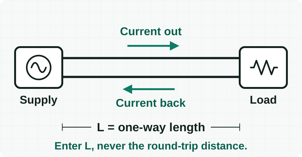
The factor 2 exists because current flows out on one conductor and back on the other, so the cable’s resistance is met twice. In a balanced three-phase circuit the three phase currents cancel in the neutral, so there is no return drop, and the drop measured between two lines is √3 times the drop along one conductor.
Single-phase loads on a three-phase supply
A 230 V load fed from a 400 V three-phase, four-wire system (or a 277 V load from 480 V) is a single-phase circuit. Choose single-phase (k = 2) and use the line-to-neutral voltage. Where a three-phase, four-wire circuit shares one neutral between many electronic loads, such as LED drivers and IT equipment, their third-harmonic currents add up in that neutral instead of cancelling, so treat it as a current-carrying conductor when you size it.
When reactance matters: the full formula
Every AC cable also has inductive reactance, X, which acts on the reactive part of the load current. The full (and standard) approximation is:
- X is the reactance of one conductor per unit length.
- cos φ is the load’s power factor, and sin φ = √(1 − cos² φ).
On small cables X is tiny next to R, and because R cos φ + X sin φ is then smaller than R, the simple formula slightly overestimates the drop: it is the conservative choice. On large cables R falls but X stays at roughly 0.08 Ω/km for a multicore cable at 50 Hz. Single conductors in conduit have more: NEC Chapter 9, Table 9 gives about 0.04 Ω per 1000 ft (0.13 Ω/km) at 60 Hz. At a power factor of 0.85, the resistance-only figure starts to read low at about 95 mm² or 1/0 AWG. It is about 7% low at 120 mm², 16% at 185 mm² and 23% at 240 mm²; in AWG sizes, about 8% at 2/0, 17% at 4/0 and 39% at 500 kcmil.
The calculator applies the full formula whenever you enter a power factor below 1. For metric sizes it uses typical reactance for a multicore cable (or single-core cables touching in trefoil); for AWG it uses NEC Table 9 values for PVC or aluminum conduit. Single-core cables laid flat or spaced apart, and conductors in steel conduit, have higher reactance, so take those figures from the manufacturer or your code’s tables. Very large conductors also have a slightly higher AC resistance than DC resistance because of skin effect (about 1% at 240 mm² and 7% at 630 mm²); the calculator adds it using the IEC 60287-1-1 method. A cable maker’s data sheet is more exact still: its AC resistance at the operating temperature includes skin effect and the proximity effect of the other cores. Enter it under Conductor resistance and choose AC at conductor temp., and the calculator uses it exactly as entered.
Where R comes from
Conductor resistance is published in standard tables. The calculator uses:
- IEC 60228 maximum DC resistance at 20 °C for metric sizes (mm²), the basis of cables sold in the UK, Europe and much of the world. Many countries publish it under their own number, such as BS EN 60228 in the UK and GB/T 3956 in China. India’s conductor standard, IS 8130:2013, gives the same values and also lists aluminum from 1.5 mm².
- Two classes of copper conductor. Class 1 (solid) and class 2 (stranded) are used for fixed wiring and power cables. Class 5 (flexible) is used for cords and for much of the house wire sold in India, and from 1 to 6 mm² its resistance is 7–10% higher: 7.98 Ω/km instead of 7.41 Ω/km for 2.5 mm². Choose it under Conductor type.
- NEC Chapter 9, Table 8 DC resistance at 75 °C for AWG and kcmil sizes, used across North America.
- Your own value, if you enter one under Conductor resistance. A DC value at 20 °C is corrected to the conductor temperature like a table value; an AC value at the conductor temperature is used as entered.
Resistance rises as a conductor warms up, so a 20 °C table value is corrected to the temperature the cable will actually run at:
- α is the temperature coefficient referred to 20 °C: 0.00393 per °C for copper and 0.00403 per °C for aluminum.
- T is the conductor temperature in °C. Designers usually take the insulation’s maximum operating temperature, such as 70 °C for PVC or 90 °C for XLPE, which gives a conservative answer. North American voltage drop calculations commonly use 75 °C, the basis of NEC Table 8. BS 7671 Appendix 4 also lets you correct the tabulated drop for the lower temperature of a lightly loaded cable.
NEC Table 8 values are already given at 75 °C. When you choose another temperature, the calculator converts them back to 20 °C and then applies the same correction. This matches the correction formula in the notes to Table 8 to within 0.01%.
Why the tables beat resistivity ÷ area
IEC 60228 defines each conductor size by its maximum resistance, not by its exact cross-section, so “6 mm²” is a nominal label. A simple resistivity ÷ area sum gives 2.87 Ω/km for 6 mm² copper; the standard allows up to 3.08 Ω/km, about 7% more. Using the tabulated maximum keeps your answer in line with the figures inspectors and code books use.
Two shortcuts you will see in practice
US circular-mil method. Many North American references write the single-phase formula with the conductor’s area in circular mils (CM, from NEC Table 8) and a constant K, the resistance of a 1 circular-mil conductor 1 foot long: about 12.9 Ω for copper and 21.2 Ω for aluminum at 75 °C. Use 1.732 instead of 2 for three-phase.
For 12 AWG (6,530 cmil), K ÷ CM is 1.98 Ω per 1000 ft, the same as Table 8, so both methods give the same answer. Like the simple formula above, it ignores reactance, so keep it to cables of about 1/0 AWG and smaller.
UK mV/A/m method. BS 7671 Appendix 4 tabulates the drop per amp per meter for each cable type, already at the conductor’s maximum operating temperature and with the factor 2 or √3 built in. Ib is the design current:
For 6 mm² two-core PVC cable the value is 7.3 mV/A/m. Above 16 mm², the tables give separate r, x and z values; use z when the load’s power factor is unknown.
Conductor resistance tables
These are the values the calculator uses, for one conductor. The figures at 20 °C are the maximum resistance each standard allows. The figures at 70 °C and 90 °C, the usual limits for PVC and XLPE insulation, are worked out from them with the temperature formula above (α = 0.00393 for copper, 0.00403 for aluminum).
Copper conductors in mm²
Resistance in Ω/km, from IEC 60228 and IS 8130:2013. Class 1–2 is solid or stranded wire for fixed wiring; class 5 is flexible.
| Size | Class 1–2 at 20 °C | Class 1–2 at 70 °C | Class 1–2 at 90 °C | Class 5 at 20 °C | Class 5 at 70 °C |
|---|---|---|---|---|---|
| 0.5 mm² | 36.0 | 43.1 | 45.9 | 39.0 | 46.7 |
| 0.75 mm² | 24.5 | 29.3 | 31.2 | 26.0 | 31.1 |
| 1 mm² | 18.1 | 21.7 | 23.1 | 19.5 | 23.3 |
| 1.5 mm² | 12.1 | 14.5 | 15.4 | 13.3 | 15.9 |
| 2.5 mm² | 7.41 | 8.87 | 9.45 | 7.98 | 9.55 |
| 4 mm² | 4.61 | 5.52 | 5.88 | 4.95 | 5.92 |
| 6 mm² | 3.08 | 3.69 | 3.93 | 3.30 | 3.95 |
| 10 mm² | 1.83 | 2.19 | 2.33 | 1.91 | 2.29 |
| 16 mm² | 1.15 | 1.38 | 1.47 | 1.21 | 1.45 |
| 25 mm² | 0.727 | 0.870 | 0.927 | 0.780 | 0.933 |
| 35 mm² | 0.524 | 0.627 | 0.668 | 0.554 | 0.663 |
| 50 mm² | 0.387 | 0.463 | 0.493 | 0.386 | 0.462 |
| 70 mm² | 0.268 | 0.321 | 0.342 | 0.272 | 0.325 |
| 95 mm² | 0.193 | 0.231 | 0.246 | 0.206 | 0.246 |
| 120 mm² | 0.153 | 0.183 | 0.195 | 0.161 | 0.193 |
| 150 mm² | 0.124 | 0.148 | 0.158 | 0.129 | 0.154 |
| 185 mm² | 0.0991 | 0.119 | 0.126 | 0.106 | 0.127 |
| 240 mm² | 0.0754 | 0.0902 | 0.0961 | 0.0801 | 0.0958 |
| 300 mm² | 0.0601 | 0.0719 | 0.0766 | 0.0641 | 0.0767 |
| 400 mm² | 0.0470 | 0.0562 | 0.0599 | 0.0486 | 0.0581 |
| 500 mm² | 0.0366 | 0.0438 | 0.0467 | 0.0384 | 0.0459 |
| 630 mm² | 0.0283 | 0.0339 | 0.0361 | 0.0287 | 0.0343 |
Aluminum conductors in mm²
Resistance in Ω/km for stranded (class 2) aluminum. IEC 60228 starts at 10 mm²; IS 8130 also lists 1.5 to 6 mm².
| Size | At 20 °C | At 70 °C | At 90 °C | Listed in |
|---|---|---|---|---|
| 1.5 mm² | 18.1 | 21.7 | 23.2 | IS 8130 only |
| 2.5 mm² | 12.1 | 14.5 | 15.5 | IS 8130 only |
| 4 mm² | 7.41 | 8.90 | 9.50 | IS 8130 only |
| 6 mm² | 4.61 | 5.54 | 5.91 | IS 8130 only |
| 10 mm² | 3.08 | 3.70 | 3.95 | IEC 60228 and IS 8130 |
| 16 mm² | 1.91 | 2.29 | 2.45 | IEC 60228 and IS 8130 |
| 25 mm² | 1.20 | 1.44 | 1.54 | IEC 60228 and IS 8130 |
| 35 mm² | 0.868 | 1.04 | 1.11 | IEC 60228 and IS 8130 |
| 50 mm² | 0.641 | 0.770 | 0.822 | IEC 60228 and IS 8130 |
| 70 mm² | 0.443 | 0.532 | 0.568 | IEC 60228 and IS 8130 |
| 95 mm² | 0.320 | 0.384 | 0.410 | IEC 60228 and IS 8130 |
| 120 mm² | 0.253 | 0.304 | 0.324 | IEC 60228 and IS 8130 |
| 150 mm² | 0.206 | 0.248 | 0.264 | IEC 60228 and IS 8130 |
| 185 mm² | 0.164 | 0.197 | 0.210 | IEC 60228 and IS 8130 |
| 240 mm² | 0.125 | 0.150 | 0.160 | IEC 60228 and IS 8130 |
| 300 mm² | 0.100 | 0.120 | 0.128 | IEC 60228 and IS 8130 |
| 400 mm² | 0.0778 | 0.0935 | 0.0997 | IEC 60228 and IS 8130 |
| 500 mm² | 0.0605 | 0.0727 | 0.0776 | IEC 60228 and IS 8130 |
| 630 mm² | 0.0469 | 0.0564 | 0.0601 | IEC 60228 and IS 8130 |
AWG and kcmil conductors
Resistance at 75 °C, in Ω per 1000 ft and Ω per km, from NEC Chapter 9, Table 8 (stranded conductors, uncoated copper). The NEC lists aluminum from 12 AWG.
| Size | Area in sq mm | Copper per 1000 ft | Copper per km | Aluminum per 1000 ft | Aluminum per km |
|---|---|---|---|---|---|
| 18 AWG | 0.823 | 7.95 | 26.1 | — | — |
| 16 AWG | 1.31 | 4.99 | 16.4 | — | — |
| 14 AWG | 2.08 | 3.14 | 10.3 | — | — |
| 12 AWG | 3.31 | 1.98 | 6.50 | 3.25 | 10.7 |
| 10 AWG | 5.26 | 1.24 | 4.07 | 2.04 | 6.69 |
| 8 AWG | 8.37 | 0.778 | 2.55 | 1.28 | 4.20 |
| 6 AWG | 13.3 | 0.491 | 1.61 | 0.808 | 2.65 |
| 4 AWG | 21.1 | 0.308 | 1.01 | 0.508 | 1.67 |
| 3 AWG | 26.7 | 0.245 | 0.804 | 0.403 | 1.32 |
| 2 AWG | 33.6 | 0.194 | 0.636 | 0.319 | 1.05 |
| 1 AWG | 42.4 | 0.154 | 0.505 | 0.253 | 0.830 |
| 1/0 AWG | 53.5 | 0.122 | 0.400 | 0.201 | 0.659 |
| 2/0 AWG | 67.4 | 0.0967 | 0.317 | 0.159 | 0.522 |
| 3/0 AWG | 85.0 | 0.0766 | 0.251 | 0.126 | 0.413 |
| 4/0 AWG | 107 | 0.0608 | 0.199 | 0.100 | 0.328 |
| 250 kcmil | 127 | 0.0515 | 0.169 | 0.0847 | 0.278 |
| 300 kcmil | 152 | 0.0429 | 0.141 | 0.0707 | 0.232 |
| 350 kcmil | 177 | 0.0367 | 0.120 | 0.0605 | 0.198 |
| 400 kcmil | 203 | 0.0321 | 0.105 | 0.0529 | 0.174 |
| 500 kcmil | 253 | 0.0258 | 0.0846 | 0.0424 | 0.139 |
| 600 kcmil | 304 | 0.0214 | 0.0702 | 0.0353 | 0.116 |
| 750 kcmil | 380 | 0.0171 | 0.0561 | 0.0282 | 0.0925 |
| 1000 kcmil | 507 | 0.0129 | 0.0423 | 0.0212 | 0.0696 |
Reading a cable data sheet
Cable makers list the maximum DC resistance at 20 °C, which matches these tables, and for power cables often the AC resistance and reactance at the maximum operating temperature. The AC figure includes skin and proximity effect for that exact cable, so it is the best value to enter for large cables.
Worked example 1: a 230 V radial circuit
A 32 A single-phase load is fed through 25 m of 6 mm² copper cable with PVC insulation (70 °C) from a 230 V supply.
- Find the table resistance. IEC 60228 gives 3.08 Ω/km at 20 °C for 6 mm² copper.
- Correct it to 70 °C. 3.08 × [1 + 0.00393 × (70 − 20)] = 3.685 Ω/km.
- Apply the single-phase formula. VD = 2 × 32 A × 25 m × 3.685 Ω/km ÷ 1000 = 5.90 V.
- Express it as a percentage. 5.90 ÷ 230 × 100 = 2.56%.
Result: the load sees about 224 V. BS 7671 judges the drop from the origin of the installation to the load, and for a non-lighting circuit on a public supply that budget is 5%, or 11.5 V. This circuit uses 2.56% of it, leaving 2.44% (about 5.6 V) for the meter tails and any sub-main upstream. The cable itself dissipates about 189 W at full load, a useful reminder that voltage drop is also an energy cost.
2.56%
Voltage drop for 32 A through 25 m of 6 mm² copper at 230 V. BS 7671’s tabulated value for the same cable (7.3 mV/A/m) gives 7.3 × 32 × 25 ÷ 1000 = 5.84 V, within about 1% of this result.
Worked example 2: a 120 V circuit in feet and AWG
A 16 A load at the end of a 100 ft run of 12 AWG copper on a 120 V circuit, with conductors at 75 °C.
- NEC Chapter 9, Table 8 lists 12 AWG stranded copper at 1.98 Ω per 1000 ft at 75 °C.
- VD = 2 × 16 A × 100 ft × 1.98 Ω ÷ 1000 ft = 6.34 V.
- VD% = 6.34 ÷ 120 × 100 = 5.28%.
Result: too much. The outlet sees under 114 V at full load. Here is how the larger sizes compare:
| Conductor | Resistance at 75 °C | Voltage drop | % of 120 V |
|---|---|---|---|
| 12 AWG | 1.98 Ω/1000 ft | 6.34 V | 5.28% |
| 10 AWG | 1.24 Ω/1000 ft | 3.97 V | 3.31% |
| 8 AWG | 0.778 Ω/1000 ft | 2.49 V | 2.07% |
10 AWG is still above the 3% branch-circuit guideline, and it only meets the 5% total if the feeder upstream drops less than 1.69%. 8 AWG meets 3% on its own and leaves 2.93% for the feeder.
In the US, the larger conductor brings a second change. NEC 250.122(B) requires a wire-type equipment grounding conductor to grow in proportion to the circular-mil area of the circuit conductors. Going from 12 AWG (6,530 cmil) to 8 AWG (16,510 cmil) multiplies the area by 2.53, so the 12 AWG grounding conductor of a 20 A circuit becomes 8 AWG as well. Standard 20 A receptacles don’t take 8 AWG, so the run is usually spliced to short 12 AWG pigtails at the box.
Lower voltage hurts twice
For the same load power, halving the voltage doubles the current, which doubles the volts lost, and those volts are then a share of a supply half as large. The percentage drop rises four times. The 1.92 kW load in this example loses 5.28% at 120 V; on the same cable at 240 V it would lose 1.32%.
Worked example 3: a three-phase feeder
A balanced 40 A three-phase load is supplied at 400 V through 80 m of 16 mm² copper cable (70 °C).
- IEC 60228: 16 mm² copper = 1.15 Ω/km at 20 °C → 1.376 Ω/km at 70 °C.
- VD = √3 × 40 A × 80 m × 1.376 Ω/km ÷ 1000 = 7.63 V line-to-line.
- VD% = 7.63 ÷ 400 × 100 = 1.91%.
Result: inside the 3% limit for a single feeder in Canada, and it leaves 3.09% of a 5% total for the final circuits downstream. At 16 mm² reactance is negligible, so the resistance-only result is accurate, and slightly conservative if the load’s power factor is below 1.
Worked example 4: a large feeder, where reactance matters
A 300 A three-phase load with a power factor of 0.85 is fed at 400 V, 50 Hz, through 150 m of 240 mm² four-core copper cable with PVC insulation (70 °C).
- Resistance. 0.0754 Ω/km at 20 °C → 0.0902 Ω/km at 70 °C. Skin effect adds about 1% at this size: R = 0.0911 Ω/km.
- Reactance. About 0.078 Ω/km, typical for a multicore cable at 50 Hz (take the exact figure from the manufacturer’s data sheet).
- Combine with the power factor. cos φ = 0.85, so sin φ = 0.527. R cos φ + X sin φ = 0.0911 × 0.85 + 0.078 × 0.527 = 0.0775 + 0.0411 = 0.1185 Ω/km.
- Apply the formula. VD = √3 × 300 A × 150 m × 0.1185 Ω/km ÷ 1000 = 9.24 V, or 2.31% of 400 V.
Result: resistance alone (power factor left at 1) gives 7.10 V, or 1.78%: 23% less than the real figure. On a 5% budget that difference decides whether the final circuits downstream still fit. To try it, set the calculator to three-phase, 240 mm², 150 m, 300 A, 400 V and a power factor of 0.85. It also shows that 185 mm² is the smallest size within 3% on this run.
How much voltage drop is acceptable?
Limits differ by country, and so does their legal weight. The calculator’s Standard list uses the figures in this table:
| Region | Rule | Each circuit or section | Total, supply to load |
|---|---|---|---|
| IEC countries | IEC 60364-5-52, Annex G (informative) | No separate figure | 3% lighting, 5% other uses, from the origin of the installation (public supply); 6% and 8% (private supply) |
| India | National Electrical Code of India, SP 30:2023, clause 4.3.10.1 (recommended) | No separate figure | 3% lighting, 5% other uses, from the origin of the installation (public supply); 6% and 8% (private supply); 2% for solar PV |
| China | GB 50052-2009, clause 5.0.4 (recommended) | No separate figure | Voltage at the equipment terminals within ±5% of rated (motors, general lighting); +5% / −10% for emergency, road and security lighting |
| UAE (Dubai) | DEWA Regulations 2017, clause 4.2.3 (mandatory) | No separate figure | 4%, from the point of supply to any point |
| UK | BS 7671 Reg. 525 and Appendix 4 (deemed to satisfy) | No separate figure | 3% lighting, 5% other uses, from the origin of the installation (public supply); 6% and 8% (private supply) |
| France | NF C 15-100, section 525 (mandatory standard) | No separate figure | 3% lighting, 5% other uses, from the origin (public LV network); 6% and 8% (private HV/LV substation) |
| Germany | DIN 18015-1 (homes, recommended); VDE-AR-N 4100; DIN VDE 0100-520, Annex G | 0.5% from the house connection to the meter (VDE-AR-N 4100) | 3% from the meter to any outlet in homes (DIN 18015-1); otherwise 3% lighting, 5% other uses |
| Spain | REBT, ITC-BT-19 and ITC-BT-15 (mandatory) | Individual feeder: 0.5%, 1% or 1.5% (ITC-BT-15) | Under 3% in dwellings; 3% lighting, 5% other uses elsewhere; 4.5% and 6.5% from an own HV/LV transformer |
| Italy | CEI 64-8, clause 525 (recommended) | No separate figure | 4%, from the origin of the installation to any appliance |
| United States | NEC informational notes (advisory); energy codes such as ASHRAE 90.1 and California Title 24 make the total mandatory for many buildings | 3% | 5%, feeder and branch combined |
| Canada | CEC Rule 8-102 (mandatory) | 3% | 5%, from the supply side of the consumer’s service |
| Mexico | NOM-001-SEDE-2012, notes to 210-19 and 215-2 (informative) | 3% | 5%, feeder and branch combined |
| Brazil | ABNT NBR 5410:2004, 6.2.7 | 4% in any terminal circuit | 5% from the delivery point (public LV supply); 7% from an own transformer or generator |
| South Africa | SANS 10142-1, clauses 5.3.2 and 6.2.7 (mandatory) | No separate figure | 5%, from the point of supply to any outlet or fixed appliance |
| Australia and New Zealand | AS/NZS 3000, Clause 3.6 (mandatory) | No separate figure | 5% from the point of supply; 7% where a dedicated substation on the premises supplies the installation |
The NEC does have binding limits in two places. Article 647 (sensitive electronic equipment) caps the drop at 1.5% on a branch circuit and 2.5% for feeder and branch combined, with tighter figures for receptacle circuits. Section 695.7 (fire pumps) allows no more than 15% below rated voltage at the controller while the motor starts, and 5% while it runs at 115% of full-load current.
BS 7671, IEC 60364 and SP 30 allow more in two cases. Where the installation has its own private supply, the totals rise to 6% for lighting and 8% for other uses, because the supply voltage is then under the installer’s control. Even then, the drop within each final circuit should, as far as possible, stay within the 3% and 5% public-supply values. All three also let you add 0.005% per meter of wiring beyond 100 m, up to 0.5% extra.
India’s figures come from the National Electrical Code. SP 30:2023 (Part 1, Section 14, Table 5) adopts the IEC 60364-5-52 values above, with the same private-supply and 100 m allowances. Its calculation method is the full formula used in this calculator, with defaults of a 0.8 power factor and 0.08 mΩ/m reactance when the details are unknown. IS 732, the Indian wiring code, sets no percentage of its own in its 1989 edition: clause 8.2.2 asks only that the drop suit the safe functioning of the equipment.
Important
Equipment rules can be stricter than the general limit. Motor manufacturers, fire pump rules and sensitive electronics often set their own voltage tolerance. Check the equipment documentation, not just the wiring code.
Using the calculator in your country
Choose your code under Standard. The calculator then sets the wire size unit, the usual single-phase and three-phase voltages, the frequency, the conductor temperature and the list of limits, and names the code’s conductor standard in the working. It changes the voltage and temperature only while they still hold the previous code’s defaults, so values you have typed stay. Each limit in the list says what it covers, and the result says where the limit is measured from.
International: IEC 60364
Choose IEC 60364 when your country is not listed. Most national wiring rules are based on IEC 60364, including the HD 60364 series used across Europe. Annex G of IEC 60364-5-52 recommends 3% for lighting and 5% for other uses from the origin of the installation, or 6% and 8% with a private supply. Saudi Arabia’s SBC 401, for example, adapts IEC 60364 for a 60 Hz supply: choose IEC 60364, set 60 Hz, and check the limit in SBC 401 section 52-5.
Asia and the Middle East
India: SP 30:2023 and IS 8130
The National Electrical Code of India (SP 30:2023, Part 1/Sec 14, Table 5) recommends 3% for lighting and 5% for other uses from the origin of the installation, 6% and 8% with a private supply, and 2% for solar PV (Part 8). Clause 3.0.2 gives 240 V single-phase and 415 V three-phase, but many supplies are quoted as 230 V and 400 V, so enter your declared voltage. Flexible house wires (IS 694, FR or FRLS) usually have class 5 conductors: choose Flexible (class 5). For 16 A over 30 m of 2.5 mm² wire at 230 V and 70 °C, class 5 gives 9.17 V (3.99%), against 8.51 V (3.70%) with class 2 values. Aluminum is accepted from 1.5 mm², because IS 8130 lists it.
China: GB 50052
China’s GB 50052-2009 (clause 5.0.4) sets no figure for the cable alone. It limits the voltage at the equipment terminals: within ±5% of rated for motors, general lighting and other equipment, and +5% / −10% for emergency, road and security lighting or small areas far from the substation. That band includes the supply’s own deviation, so keep the cable drop well inside it. The usual supply is 220 V / 380 V at 50 Hz, and conductors follow GB/T 3956, which is identical to IEC 60228. YJV power cables (XLPE) run at up to 90 °C, BV building wire (PVC) at 70 °C.
UAE (Dubai): DEWA Regulations
The DEWA Regulations for Electrical Installations (2017, clause 4.2.3) cap the drop at 4% of the nominal voltage from the point of supply to any point of the installation. DEWA supplies 230 V / 400 V at 50 Hz (±10%). The same regulations set minimum sizes of 2.5 mm² for lighting circuits and 4 mm² for socket-outlet circuits, so check the minimum size as well as the drop.
Europe
United Kingdom: BS 7671
BS 7671 Appendix 4 (deemed to satisfy Regulation 525) allows 3% for lighting and 5% for other uses from the origin of the installation on a public supply, or 6% and 8% with a private supply. Its tables give the drop in mV/A/m at the conductor’s maximum operating temperature: 70 °C for thermoplastic (PVC) cables and 90 °C for thermosetting (XLPE) cables, so set the same temperature here. For 6 mm² two-core PVC cable the table value is 7.3 mV/A/m, within about 1% of this calculator (worked example 1).
France: NF C 15-100
NF C 15-100 (section 525) limits the drop from the origin of the installation to 3% for lighting and 5% for other uses on the public LV network, or 6% and 8% when a private HV/LV substation supplies the installation. The supply is 230 V / 400 V at 50 Hz. Choose 90 °C for U-1000 R2V cables (XLPE) and 70 °C for H07V-U and H07V-R wires (PVC).
Germany: DIN 18015-1 and DIN VDE 0100-520
In homes, DIN 18015-1 recommends no more than 3% from the meter to any outlet, worked out with the rated current of the upstream protective device rather than the load: enter the breaker rating (for example 16 A) as the load current. VDE-AR-N 4100 allows 0.5% in the unmetered main supply between the house connection box and the meter. Other buildings follow DIN VDE 0100-520, Annex G: 3% for lighting and 5% for other uses. NYM-J cables (PVC) run at up to 70 °C.
Spain: REBT (ITC-BT-19)
Spain’s low-voltage regulation (REBT, Royal Decree 842/2002) is mandatory. ITC-BT-19 limits the drop from the origin of the interior installation to under 3% in dwellings, and to 3% for lighting and 5% for other uses elsewhere; an industrial installation with its own HV/LV transformer may use 4.5% and 6.5% from the transformer output. ITC-BT-15 limits the individual feeder (derivación individual) separately: 0.5%, 1% or 1.5%, depending on how the meters are grouped.
Italy: CEI 64-8
CEI 64-8 (Part 5, clause 525) recommends no more than 4% of the nominal voltage from the origin of the installation to any appliance, unless the client agrees another value. The supply is 230 V / 400 V at 50 Hz. FS17 single-core wires (PVC) run at up to 70 °C, and FG16 power cables (HEPR) at 90 °C.
The Americas
United States: NEC
The NEC’s 3% (branch circuit or feeder) and 5% (both together) are informational notes, so they are advisory unless your energy code or the authority having jurisdiction adopts them; ASHRAE 90.1 and California Title 24 make the 5% total mandatory in many buildings. Article 647 (sensitive electronics, 1.5% and 2.5%) and section 695.7 (fire pumps) are binding. Sizes are AWG and kcmil at 75 °C (NEC Chapter 9, Table 8). For a 277 V lighting circuit from a 480Y/277 V panel, choose single-phase and enter 277 V. If you upsize for voltage drop, NEC 250.122(B) makes the equipment grounding conductor grow in proportion.
Canada: CEC
CEC Rule 8-102 is mandatory: 3% in any feeder or branch circuit and 5% in total from the supply side of the consumer’s service. Base the check on the connected load or, if that is not known, 80% of the overcurrent device rating: 12 A for a 15 A breaker. Homes are usually supplied at 120/240 V and commercial buildings at 120/208 V or 347/600 V, all at 60 Hz.
Mexico: NOM-001-SEDE-2012
NOM-001-SEDE-2012 gives 3% for a branch circuit or feeder and 5% for both together, in informative notes to sections 210-19 and 215-2, as the NEC does. The usual supply is 220Y/127 V at 60 Hz, and sizes are AWG and kcmil. At 127 V a 3% drop is only 3.8 V, so long branch circuits often need a larger size than the current alone suggests.
Brazil: NBR 5410
NBR 5410 (6.2.7) allows at most 4% in any terminal circuit, and in total 5% from the delivery point on a public low-voltage supply, or 7% from the terminals of an own MV/LV transformer or generator. The supply is 127/220 V or 220/380 V at 60 Hz, depending on the region, and conductors follow NBR NM 280, which is based on IEC 60228.
Africa and Oceania
South Africa: SANS 10142-1
SANS 10142-1, which the Occupational Health and Safety Act makes compulsory, limits the drop to 5% from the point of supply to any outlet or fixed appliance: 11.5 V at 230 V and 20 V at 400 V. The 5% must include any reticulation after the point of supply, such as a housing scheme with submetering. Its voltage drop tables assume conductors at 70 °C for PVC cables, so use 70 °C here to compare.
Australia and New Zealand: AS/NZS 3000
AS/NZS 3000 (clause 3.6.2) is mandatory: no more than 5% from the point of supply, or 7% where a substation on the premises supplies the installation. AS/NZS 3008.1.1 gives the drop as Vc in mV/A·m at the cable’s operating temperature, 75 °C for V-75 PVC and 90 °C for X-90 XLPE; set the same temperature here to compare. The supply is 230 V / 400 V at 50 Hz.
Important notes before you rely on a result
- Enter the power factor on large cables. From about 95 mm² or 1/0 AWG upward, reactance pushes the real drop above the resistance-only figure at typical motor and mixed-load power factors: by nearly a quarter at 240 mm² (see worked example 4).
- Use the real load current. For a final circuit, that is usually the design current. In Canada, Rule 8-102 bases the check on the connected load if it is known, and otherwise on 80% of the rating of the overcurrent device protecting the circuit.
- Use the right conductor class. From 1 to 6 mm², flexible (class 5) wire has 7–10% more resistance than solid or stranded wire of the same size, so a house circuit worked out with class 2 values reads low.
- Check motor starting separately. A direct-on-line start draws about six to eight times full-load current at a power factor of only about 0.2 to 0.4. The steady-state limits above do not apply during starting. Instead, check the dip against what the motor, its contactor and the other loads can tolerate, often 10% to 15% at the motor terminals. Enter the starting current and starting power factor in the calculator to estimate it.
- Remember every segment. The drop in the service cable, the feeder and the final circuit adds up. Budget the total, not just the last run.
- DC systems follow the same math. Solar strings, battery banks and 12 V or 48 V systems use the single-phase formula with k = 2 and no reactance. Because their voltage is low, a few volts of drop is a large percentage, so designers aim lower. For solar PV, India’s SP 30:2023 (Part 8) recommends no more than 2% from the most remote module to the inverter at maximum power, and less than 2% in total on the AC side from the inverter to the point of common coupling.
- Voltage drop is not the only check. A cable must also carry the current without overheating (ampacity or current-carrying capacity) and clear faults quickly enough. Size for all three.
How to reduce voltage drop
- Increase the conductor size. Resistance falls roughly in proportion to cross-sectional area, so going from 6 mm² to 10 mm² cuts the drop by about 40%. In the US, remember that NEC 250.122(B) makes the equipment grounding conductor grow in proportion.
- Run conductors in parallel. Two identical sets per phase halve the drop, which is how most large feeders are built. Parallel sets must match in length, material, size and insulation, and codes set a minimum size (1/0 AWG in the NEC).
- Shorten the route. Move the distribution board closer to the load, or feed from a nearer source.
- Raise the distribution voltage. For the same power and conductor size, supplying a remote building at 400 V three-phase instead of 230 V single-phase cuts the percentage drop to about one-sixth.
- Improve the power factor. Correcting an inductive load lowers both the current and the reactive part of the drop. Enter the corrected power factor in the calculator to see the effect, and use the power factor correction calculator to size the capacitors.
- Split the load. Two circuits each carrying half the current have half the drop each.
Frequently asked questions
Which standards and countries does this calculator support?
Fifteen wiring codes: IEC 60364 (international), India (SP 30:2023 with IS 8130), China (GB 50052), the UAE (DEWA), the UK (BS 7671), France (NF C 15-100), Germany (DIN 18015-1 and DIN VDE 0100-520), Spain (REBT), Italy (CEI 64-8), the United States (NEC), Canada (CEC), Mexico (NOM-001-SEDE-2012), Brazil (NBR 5410), South Africa (SANS 10142-1), and Australia and New Zealand (AS/NZS 3000). For any other country choose IEC 60364, which most national rules follow, and check the limit in your local code.
Is L the one-way length or the round-trip length?
One-way. The 2 (or √3) in the formula already accounts for the return conductor. Entering the round-trip distance doubles the answer.
What size cable do I need for my run?
Enter the current, length and voltage, set your drop limit, and read Smallest size within limit in the calculator. The search starts at the usual minimum sizes for fixed wiring: 1.5 mm² copper or 10 mm² aluminum (IEC 60364-5-52), and 14 AWG copper or 12 AWG aluminum (NEC 310.3). Voltage drop only sets a minimum: the cable must also have enough current-carrying capacity for the way it is installed, and protect against faults.
How far can I run a cable before the drop is too high?
Read Longest run within limit in the calculator. For example, 6 mm² copper carrying 32 A at 230 V reaches 3% at about 29 m.
What is the resistance of 2.5 sq mm copper wire?
At 20 °C, at most 7.41 Ω/km for solid or stranded (class 1–2) wire and 7.98 Ω/km for flexible (class 5) wire, from IEC 60228 and IS 8130. At 70 °C, the usual limit for PVC insulation, that becomes about 8.87 and 9.55 Ω/km. The conductor resistance tables give every size from 0.5 to 630 mm², in aluminum too, and AWG sizes from 18 AWG to 1000 kcmil.
Can I use the resistance from a cable data sheet?
Yes. Enter it under Conductor resistance, in Ω/km for mm² sizes or Ω per 1000 ft for AWG. Choose DC at 20 °C for the maximum DC resistance that data sheets list: the calculator corrects it to the conductor temperature and adds skin effect, as it does for table values. Choose AC at conductor temp. for an AC resistance at 70 °C or 90 °C, which is used exactly as entered. If your figure is more than 25% away from the standard value for that size, the result warns you, because that usually means a unit slip.
Can I use this calculator in India?
Yes. Choose India · SP 30:2023, IS 8130 under Standard. The calculator then uses 230 V single-phase or 415 V three-phase at 50 Hz, the IS 8130:2013 conductor values and the SP 30 limits: 3% for lighting and 5% for other uses from the origin of the installation to the load, and 2% for solar PV circuits. SP 30 gives 240 V and 415 V, but supplies are often quoted as 230 V and 400 V, so type your declared voltage. Choose Flexible (class 5) for house wires, 70 °C for PVC-insulated cables and 90 °C for XLPE cables such as IS 7098. If you have the cable maker’s data sheet, enter its resistance.
Does voltage drop depend on the supply voltage?
The volts lost don’t: they depend only on current, length and conductor. The percentage does, because the same volts are a bigger share of a lower supply. For the same power, a lower voltage also means more current, which is why 12 V and 120 V circuits are so sensitive.
Does voltage drop cost money?
Yes. The lost volts become heat in the cable. In worked example 1 the cable dissipates about 189 W at full load, which is about 550 kWh a year if the circuit runs at full load eight hours a day.
Once the drop is under control, the kW, kVA and amps calculator helps you check the current a load will draw in the first place.
Sources
- IEC 60228:2023, Conductors of insulated cables (opens in a new tab) International Electrotechnical Commission
- IS 8130:2013, Conductors for insulated electric cables and flexible cords (Tables 1, 2 and 3: class 1, 2 and 5 resistance) (opens in a new tab) Bureau of Indian Standards, via Public.Resource.Org
- KEI HomeCab FR house wire data sheet (class 5 conductor resistance) (opens in a new tab) KEI Industries
- SP 30:2023, National Electrical Code of India (Part 1/Sec 3, clause 3.0.2; Part 1/Sec 14, clause 4.3.10 and Table 5; Part 8, clauses 6.1.1 and 6.2.1) (opens in a new tab) Bureau of Indian Standards, via Public.Resource.Org
- IS 732:1989, Code of practice for electrical wiring installations (clause 8.2.2, voltage drop, page 44) (opens in a new tab) Bureau of Indian Standards, via Public.Resource.Org
- IEC 60287-1-1:2023, Electric cables: calculation of the current rating (skin-effect factor) (opens in a new tab) International Electrotechnical Commission
- NFPA 70, National Electrical Code (Chapter 9 Tables 8 and 9; 250.122, 647.4, 695.7) (opens in a new tab) NFPA
- BS 7671:2018+A4:2026, Requirements for Electrical Installations (Regulation 525 and Appendix 4) (opens in a new tab) IET and BSI
- IEC 60364-5-52:2009, Selection and erection of electrical equipment: wiring systems (Annex G) (opens in a new tab) International Electrotechnical Commission
- CSA C22.1:24, Canadian Electrical Code, Part I (Rule 8-102) (opens in a new tab) CSA Group, listed by the Standards Council of Canada
- ANSI/ASHRAE/IES Standard 90.1 (Section 8.4.1, voltage drop) (opens in a new tab) ASHRAE
- California Building Energy Efficiency Standards (Title 24, Part 6) (opens in a new tab) California Energy Commission
- AS/NZS 3000:2018, Electrical installations (Wiring Rules), Clause 3.6 (opens in a new tab) Standards Australia and Standards New Zealand
- AS/NZS 3008.1.1:2025, Electrical installations: selection of cables (voltage drop, Vc) (opens in a new tab) Standards Australia and Standards New Zealand
- GB 50052-2009, Code for design of electric power supply systems (clause 5.0.4) (opens in a new tab) National standard of China, via Wikimedia Commons
- DEWA Regulations for Electrical Installations, 2017 edition (clause 4.2.3) (opens in a new tab) Dubai Electricity and Water Authority
- SBC 401, The Saudi Electrical Code, 2024 (section 52-5 and Annex G.52, contents) (opens in a new tab) Saudi Building Code National Committee
- NF C 15-100, Installations électriques à basse tension (section 525) (opens in a new tab) AFNOR
- DIN 18015-1:2020-05, Elektrische Anlagen in Wohngebäuden: Planungsgrundlagen (opens in a new tab) DIN
- VDE-AR-N 4100, Technische Anschlussregeln Niederspannung (TAR Niederspannung) (opens in a new tab) VDE FNN
- Real Decreto 842/2002, Reglamento electrotécnico para baja tensión (ITC-BT-15 and ITC-BT-19) (opens in a new tab) Boletín Oficial del Estado (Spain)
- CEI 64-8, Impianti elettrici utilizzatori (Part 5, clause 525) (opens in a new tab) Comitato Elettrotecnico Italiano
- NOM-001-SEDE-2012, Instalaciones eléctricas (utilización) (210-19 and 215-2) (opens in a new tab) Secretaría de Economía, Mexico
- ABNT NBR 5410:2004, Instalações elétricas de baixa tensão (6.2.7) (opens in a new tab) ABNT, listed by Target
- SANS 10142-1, The wiring of premises, Part 1: Low-voltage installations (clauses 5.3.2 and 6.2.7) (opens in a new tab) SABS Standards Division


